A good day to you all at mfbfreaks.nl
I have re-submitted this post as it disappeared some months back; the green Standby and the red operating neon indicators are working, and a little sound (maybe it is coming from the pre-amp).
I have replaced all the Philips Blue Electrolytic Capacitors 18 of them; I have tested the old ones and 13 of them still had good readings using a capacitor tester. I replaced the Relay as well, it is still no better.
Mains Transformer Voltage Readings Between;
A = 234 vac Input source
B = 116 vac
C = 116 vac
D = 25.6 vac
E = 25.6 vac
F = 0 vac Input source?
Notes: my meter did not identify DC only AC (maybe I needed to set the range?).
F indicates another input source?
New Philips Blue Electrolytic Capacitors fitted and Relay
Chart of Blue Electrolytic Capacitors
Hi Michael,
The first thing to check would be the voltage on the relais coil.
(the two pins seperated from the other twelve)
The voltage should be 24v dc in working mode. (put your meter in dc range)
And are the fuses ok ? Test this by measuring voltage between the fuse-ends during working mode.
You might find a ac voltage here. (set your meter to ac range, later to dc range)
Hello Herman; and thank you for your support.
Relay: In September I checked the working voltage: - With no voltage until the red Operating neon indicator comes on; then giving 10 vac there should have been 24 vdc this was not the case!
Meter would have been on auto range finder for ac/dc. That was before replacing Philips Blue Electrolytic Capacitors.
Do I need to check this again, I note your comment setting meter to vdc?
All fuses were checked using ohms meter; checking these in working mode is much more difficult?
Shouldn’t there be some input voltage on F?
Please advise.
Hi Michael, i believe the relay is ok, the red led comes on, you've changed it already and do you also hear or see it come on when there is enough input signal?
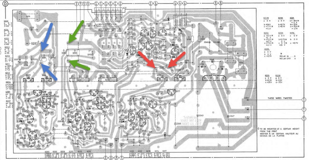
Can you measure the bias current through the three amps as it is right now? just to check there is any. You can measure it on the solder side of the big print, you have to check the servicedoc to find out the exact points and be carefull not to slip the probe's.
(The current is measured by means of a DC millivoltage over the emitter resistors, so you're not actually measuring current but voltage instead so the Multimeter is to be set on Voltage measuring and if it's there: mV)
It is possible to misallign some of the connectors on the PCB 😯 i hope this is not the case here.
Is the input volume knob set ok?
Did you check the solderside of the input PCB (and the amp pcb) to see if there are perhaps any open solderpoints?
Hello Remi and thank you for your help;
Turning the Input Sensitive Control (No 5) one way you can hear a small amount of sound and turning it the other way (speaker amp) no sound at all.
Preparation: To measure the bias current, I think you mean voltages not current. I need to know where to put my probes to do this, normally one probe to neutral and the other to a positive source, is it one voltage test only?
I have posted some drawings of the main board (if these are not the right ones let me know and I will change them) because I need instructions where to clip each probe to undertake this test, how about if you take a screen shot of the one, then open it up with an editing photo program and either enter a crow foot/arrow or open with paint and put a square over the connections, please use brown and blue to identify polarity then post it back to me to see?
Note I have put an example in the first drawing top right corner, in brown and blue.
The procedure: Set the meter to DC millivolts with crocodile clips attached to the probes; connect probes to component tails on the PC board.
Connect the speaker (only) to the mains supply 240v and note the reading.
My last test; all cable connections had been reconnected to the board correctly and the Input Sensitive Control had not been altered.
All solder joints had been inspected with a magnifier for unfilled solder joints.
Kind regards Michael
well.. the current is of course related to the voltage over the resistors, these voltages are given in de servicedoc.

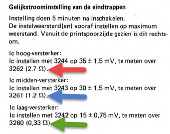
The voltage over these resistors are to be measured and you could also set them to right value by adjusting the mentioned variable resistor (3244,3243,3242).
So Red is for the high note amp, Blue is the mid-note and Green will be the low-note amp.
I always measure these setting at the solder site of the board, with the amp board mounted to the backplane.
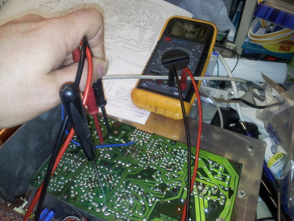
I even found an older picture of me actualy adjusting the bias current in the Low amp, the screwdriver is in 3242
but how about the relay? does it switch?
That’s very helpful Remi; yes I can see how you made the adjustment from the solder side, if you look at the other side of the board it looks like you can adjust also from there (which would be of no use in this situation), see my post of Thursday 18 Dec.
Can you please confirm; the positive probe goes to the side showing the diamond/lozenge shape ◊ on the drawing, if this is not so would you kindly mark your drawing and the mains supply will be on and not connected to the amp to undertake the test.
The servicedoc that I have; isn’t in English, is there an English version?
I have edited my post (as it was confusing) of the Tuesday, 23 December 2014 regarding the relay; the working voltage to it was incorrect 10 vac!
Kind regards Michael
I really don't know, and it is not that important either as long as you use a digital multimeter which i think you have.
In the picture you can see the reading on the meter is 15mV, if i would have swapped the probe's the reading would still be 15mV, now starting with a minus (-).
@michael wrote:
Hello Herman; and thank you for your support.
Relay: In September I checked the working voltage: - With no voltage until the red Operating neon indicator comes on; then giving 10 vac there should have been 24 vdc this was not the case!
So the relay doesn't do anything?Meter would have been on auto range finder for ac/dc. That was before replacing Philips Blue Electrolytic Capacitors.
Before replacing the caps was the relay in good working order or do you mean you had the same results as it does now?
Do I need to check this again, I note your comment setting meter to vdc?All fuses were checked using ohms meter; checking these in working mode is much more difficult?
If the fuse is good you would measure a zero or very close to zero voltage over the fuseShouldn’t there be some input voltage on F?
don't know yet
Please advise.
I can't tell from the pcture if this relay has the little thingy to mechaniacally close the contacts, it seems so but i'm not sure.
If this is the case you could close it by hand and if the rest of the box is ok you would hear music. Probably wise to turn down the volume before to prevent a heart attack 😯
If the box would play now is the big question why it gives you such strange voltages on the relay coil.
I don't know if there is a English version of the doc, can't imagine there wouldn't be but i don't have it.
Thank you Remi for clarifying probe connections, I will quote, “measure the bias current through the three amps as it is right now” on Monday, please could you give me further tasks to undertake at the same time.
Could we proceed to investigate the 10 volt ac (upstream) at the relay and the 0 volts on F see my first post.
Your answers: 1. That’s right Remi, incorrect voltage at the relay?
2. The old relay probably would of worked if the correct voltage was there?
3. Fuses are good, will check again on Monday.
I am confident I still have a very healthy hart 8)
Kind regards Michael
Just a small warning now: Don't just close the relaiscontacts unless you are absolutely sure
that there is no DC component on any of the ampfilier outputs.
My advice here:
If you are not sure about that or do not know how to measure that: Save time with endless questions, just forget about mechaniacally closing this relais contact.
Thank you Herman for the word of caution; I wasn’t going to try that 💡
Remi; I have been thinking about the presents of ac at the relay; do you think a component has failed that changes or something to dc ❗
Finished: I used my old Fluke 73 meter as I expected it to be more accurate than my new China made meter to calibrate the bias current through the three amps are now set; see my photos.
I only could find 3 (glass) fuses and they were on the main pcb, they are good 8)
Kind regards Michael
Why buy a new China meter if you have a good Fluke ?
I wonder if the readings / vaules were adjustable ? They look good so I figure that you adjusted them.
Next step would be to measure the DC voltage on each of the relais pins (compared to ground) during working mode (sound signal applied and mains switch on) ...
A good day to you Herman, we have a few light snow showers here temp 1.2°c time 1pm.
I needed a meter to test the Philips Blue Electrolytic Capacitors, one that would test over or up to 3300μf, I looked on eBay for a Fluke used meter, there was one, the readout was designed to unplug off the base which put me off from bidding, hence I bought one that was made in China because of the price.
That’s right I had to adjust the bias current on all three they were 21 blue, 9.3 green and 31.3mv red.
All the rectification has been downstream from and including the relay is this correct?
So the input voltages will not have changed; I am getting 10 volt ac at the relay coil pins after an input signal is detected via the pre-amp, something is wrong it should be 24 vdc, until this is correct the relay will not work, isn’t this correct?
There is no input voltage on F, I tested this in the same situation as testing the bias current, is this correct, or it could be volt free connections to pass something else?
Kind regards Michael
